
Twenty-way connector
Twenty terminal cores, and the joins they leave behind. The smallest part in the series: a 1.5 mm glass-filled PBT connector where twenty terminal passages produce repeated joining traces and a solid latch root drives the local shrinkage.
- Application
- Automotive electrical
- Material
- PBT with 30 percent glass fiber (BASF Ultradur B 4300 G6)
- Method
- 3D Fill + Pack + Warp
- Focus
- Latch root, terminal joins and mating fit
- Project type
- Internal demonstration
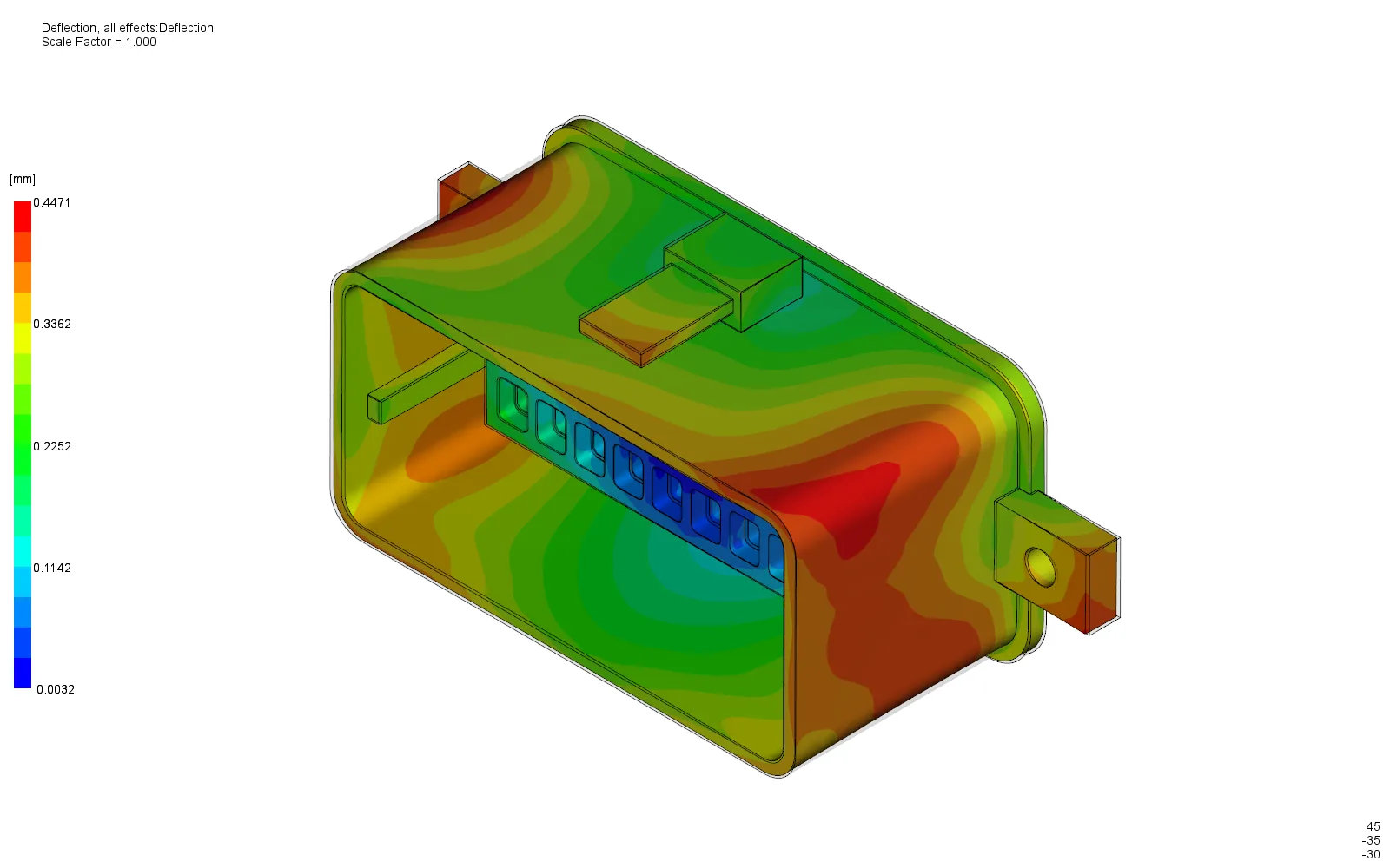
What do twenty terminal cores do to the flow, and how much does the mating face move?
Every terminal passage is a core the melt has to travel around, and every core leaves a trace where the flow closes behind it. On a twenty-way connector those traces are the dominant flow feature.
The 3D run on a validated 1,179,684-tetrahedron mesh was used to place those joins, to find where the mouth region ends up cool, and to separate mating-face movement from rear-seal movement.
84.0 x 36.0 x 31.0 mm, 1.5 mm nominal wall, 19.544 cm3: 53 features with twenty terminal passages, a mating shroud, key rails, a rear seal land, pierced mounting ears and a latch support.
A traceable engineering model.
Two-stage meshing: a Dual Domain surface first, then a 3D tetrahedral mesh generated from the corrected surface, so the screened inlet node survives into the 3D run. Gate position was screened on matched Dual Domain models, one inlet against two, before the 3D run was launched.
The 3D Fill + Pack + Warp run was solved with a single point inlet, a nominal one-second fill, switchover at 99 percent of part volume and a hold at 80 percent of filling pressure. Every plot keeps its original legend so each result can be read in its own units.
Read the result in context.
The part fills in 1.047 s with the mating mouth filling after the terminal region, at the lowest V/P pressure in the series, 22.49 MPa. Pressure falls toward that last-filled mouth and the front there is cooler than the terminal core, 254.0-261.1 degC across the part.
The terminal cores produce 1036 valid weld-angle samples, and 564 air-trap nodes mark the mouth edges and core interfaces where vent access is needed. The solid latch root dominates internal shrinkage at 12.25 percent and imprints 0.090 mm on the inner shroud wall.
Total deflection is 0.447 mm, the smallest in the series, and the mating rim closes to a 0.184 mm fitted-plane residual. Mating, terminal-entry and rear-seal surfaces still need three separate dimensional assessments.
From evidence to action.
Plan venting at the mouth edges and the terminal-core interfaces, and treat the latch root as a thermal problem rather than a shrinkage-compensation problem.
Keep dual gating open as a credible alternative and screen it against this single-inlet baseline once the terminal retention requirement is defined.
Study boundaries
- Internal demonstration on an original design; no customer project or physical trial correlation is claimed.
- These are simulation outputs, not measured production performance.
- Original teaching geometry; no OEM requirement set and no supplier service qualification.
- Ideal point inlet: physical gate, runner, sprue and nozzle losses are excluded.
- Uniform mold temperature; cooling circuits and mold blocks are not modeled.
- Warp uses a two-layer aggregated mesh (solver warning 201412); mesh sensitivity at thick junctions remains open.
- No dimensional, cosmetic or sealing pass/fail claim is made without defined functional requirements.
A similar question about your part?
Send the part, the material and the question.