
Center console bezel
A visible surface, a joining line and a bow. A PC+ABS bezel with shifter, switch and indicator openings, where the cosmetic face and the joining line above the shifter opening set the review.
- Application
- Automotive interior trim
- Material
- PC+ABS (Covestro Bayblend T85)
- Method
- 3D Fill + Pack + Warp
- Focus
- Cosmetic face and screw-tower roots
- Project type
- Internal demonstration
Where does the flow rejoin on a visible surface, and how flat does that surface stay?
On a bezel the analysis question is cosmetic before it is structural. The flow has to travel around three openings, and wherever the fronts meet again there is a line that may or may not be visible after graining and painting.
This study screens the inlet, then runs the 3D sequence to place that joining line and to measure how much the visible face bows once packing and cooling are done.
281.5 x 181.5 x 28.0 mm, 2.5 mm nominal wall, 155.307 cm3: 24 features, a drafted open-back bezel with shifter, switch and indicator openings, cored towers, ribs and locating features.
A traceable engineering model.
Two-stage meshing: a Dual Domain surface first, then a 3D tetrahedral mesh generated from the corrected surface, so the screened inlet node survives into the 3D run. Gate position was screened on matched Dual Domain models, one inlet against two, before the 3D run was launched.
The 3D Fill + Pack + Warp run was solved with a single point inlet, a nominal one-second fill, switchover at 99 percent of part volume and a hold at 80 percent of filling pressure. Every plot keeps its original legend so each result can be read in its own units.
Read the result in context.
The bezel fills in 1.064 s, with the flow rejoining above the shifter opening, and demands the highest V/P pressure in the series at 94.34 MPa. Filling is still not the clamp maximum; the packing phase is.
Volumetric shrinkage peaks at 9.04 percent at the upper tower junction, while the largest sink estimate, 0.062 mm, sits on the lower external rim. Two different mechanisms, two different locations.
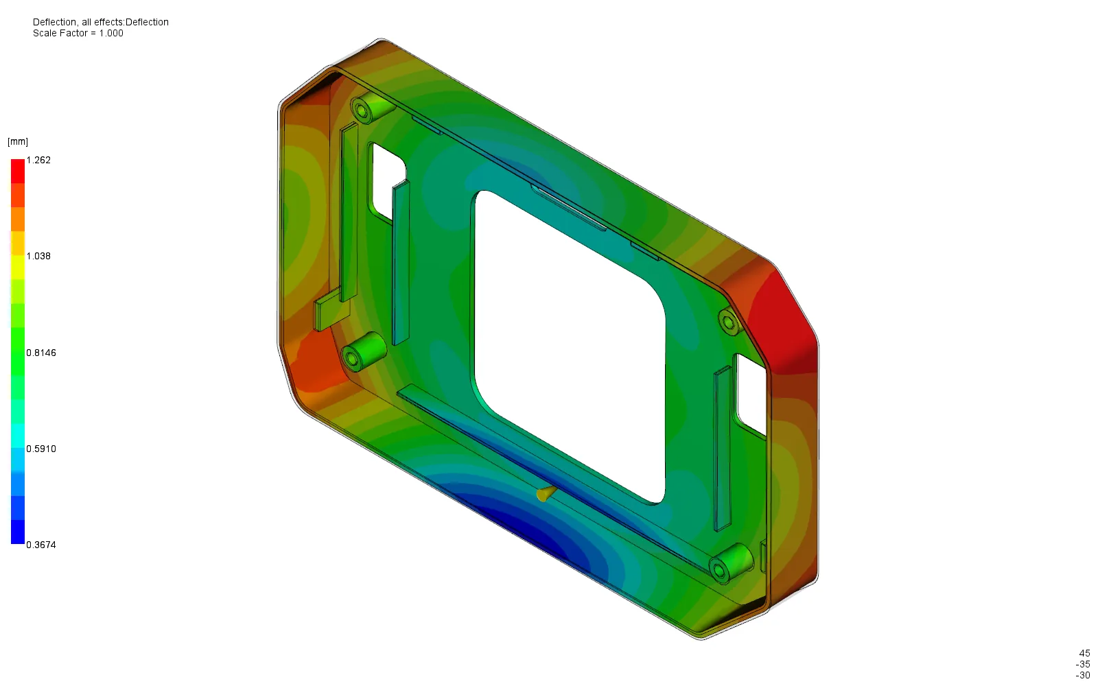
Total deflection is 1.262 mm, the smallest of the three large interior parts, but the cosmetic face still closes to a 0.986 mm residual against a fitted plane. That residual, not the global maximum, is the number a fit-and-finish review needs.
From evidence to action.
Resolve the upper-bridge joining risk before anything else; the lower central inlet is a concept baseline, not a recommendation.
Introduce a physical feed and cooling model, then validate the cosmetic-face bow and the mounting fit against defined datums and molded parts.
Study boundaries
- Internal demonstration on an original design; no customer project or physical trial correlation is claimed.
- These are simulation outputs, not measured production performance.
- Original teaching geometry; no OEM requirement set and no supplier service qualification.
- Ideal point inlet: physical gate, runner, sprue and nozzle losses are excluded.
- Uniform mold temperature; cooling circuits and mold blocks are not modeled.
- Warp uses a two-layer aggregated mesh (solver warning 201412); mesh sensitivity at thick junctions remains open.
- No dimensional, cosmetic or sealing pass/fail claim is made without defined functional requirements.
A similar question about your part?
Send the part, the material and the question.