
Radiator fan shroud
Hub-first filling, frame-last movement. A 524 mm glass-filled PA66 shroud with an annular duct, a motor hub and four support arms, where frame bow and motor-to-radiator alignment set the review.
- Application
- Automotive cooling
- Material
- PA66 with 30 percent glass fiber (BASF Ultramid A3WG6)
- Method
- 3D Fill + Pack + Warp
- Focus
- Frame bow and joining position in the motor arms
- Project type
- Internal demonstration
Does a large shroud hold the motor square to the radiator after it cools?
A fan shroud has to keep a motor concentric with a duct and both of them square to a radiator. It is a large, open frame with a heavy centre, which is a difficult shape to hold dimensionally.
The 3D run fills from a single underside hub inlet, so the study can show where the duct quadrants join and how the frame and the hub move relative to each other.
524.0 x 430.0 x 60.0 mm, 3 mm nominal wall, 664.461 cm3: 32 features, a drafted annular duct, a motor hub, four support arms, ribs and pierced radiator mounts.
A traceable engineering model.
Two-stage meshing: a Dual Domain surface first, then a 3D tetrahedral mesh generated from the corrected surface, so the screened inlet node survives into the 3D run. Gate position was screened on matched Dual Domain models, one inlet against two, before the 3D run was launched.
The 3D Fill + Pack + Warp run was solved with a single point inlet, a nominal one-second fill, switchover at 99 percent of part volume and a hold at 80 percent of filling pressure. Every plot keeps its original legend so each result can be read in its own units.
Read the result in context.
The shroud fills hub-first and ends at the outer frame at 1.052 s, at 71.88 MPa V/P pressure. The flow front runs 290.0-297.7 degC and the shear peak, 1667 per second at the 95th percentile, is at the inlet rather than along the arm paths.
Major joining occurs in the duct quadrants. The lower-pressure dual-inlet screen moves those joins into the motor arms instead, which is a trade rather than an improvement.
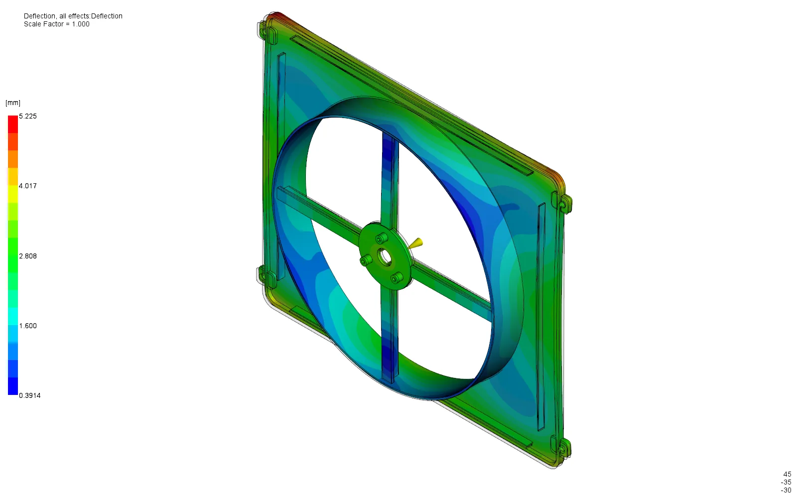
Total deflection reaches 5.225 mm on the outer frame with an 8.338 mm out-of-plane range: the motor hub and the peripheral frame move differently. Against a fitted plane the frame still carries a 6.959 mm residual.
From evidence to action.
Separate the mounting-junction thermal mass from the hub and boss sink; they are different defect mechanisms in different places.
Define motor-to-radiator alignment limits and duct-rim form requirements, then re-solve with modelled feed and cooling against them.
Study boundaries
- Internal demonstration on an original design; no customer project or physical trial correlation is claimed.
- These are simulation outputs, not measured production performance.
- Original teaching geometry; no OEM requirement set and no supplier service qualification.
- Ideal point inlet: physical gate, runner, sprue and nozzle losses are excluded.
- Uniform mold temperature; cooling circuits and mold blocks are not modeled.
- Warp uses a two-layer aggregated mesh (solver warning 201412); mesh sensitivity at thick junctions remains open.
- No dimensional, cosmetic or sealing pass/fail claim is made without defined functional requirements.
A similar question about your part?
Send the part, the material and the question.