
Headlamp rear housing
Where a large service-collar housing loses its flatness. A 386 mm mineral-filled polypropylene headlamp housing taken from gate screening through 3D filling, packing and warpage, with the seal channel and the four vehicle mounts as the review surfaces.
- Application
- Automotive lighting
- Material
- PP with 20 percent mineral filler (SABIC PPCompound PHC25/20)
- Method
- 3D Fill + Pack + Warp
- Focus
- Service-collar transitions and seal channel
- Project type
- Internal demonstration
How does a large lighting housing fill, and which surfaces move enough to matter?
A headlamp rear housing carries its function on two surfaces: the channel that takes the seal to the lens, and the mounts that locate the lamp in the vehicle. Everything else is structure around them.
This internal study screens the inlet position first, then follows one 3D run from filling to final deflection so the flow path, the pressure it demands and the deformation that follows can be read as one chain of evidence.
386 x 202 x 82 mm, 2.5 mm nominal wall, 287.204 cm3 of material: 42 features carrying service collars, cored bosses, ribs, a seal channel and four mounts.
A traceable engineering model.
Two-stage meshing: a Dual Domain surface first, then a 3D tetrahedral mesh generated from the corrected surface, so the screened inlet node survives into the 3D run. Gate position was screened on matched Dual Domain models, one inlet against two, before the 3D run was launched.
The 3D Fill + Pack + Warp run was solved with a single point inlet, a nominal one-second fill, switchover at 99 percent of part volume and a hold at 80 percent of filling pressure. Every plot keeps its original legend so each result can be read in its own units.
Read the result in context.
The cavity fills completely in 1.079 s, with the left mounting tab as the last region to fill and a V/P peak of 46.92 MPa. The flow front stays within 228-232 degC, so no cold-front claim is needed anywhere on the part.
Volumetric shrinkage peaks at 18.88 percent inside the mounting tabs, and the interior of the part needs 44.87 s to reach ejection temperature. Both point at thermal mass rather than at the flow: the tab junctions are simply thicker than the wall around them.
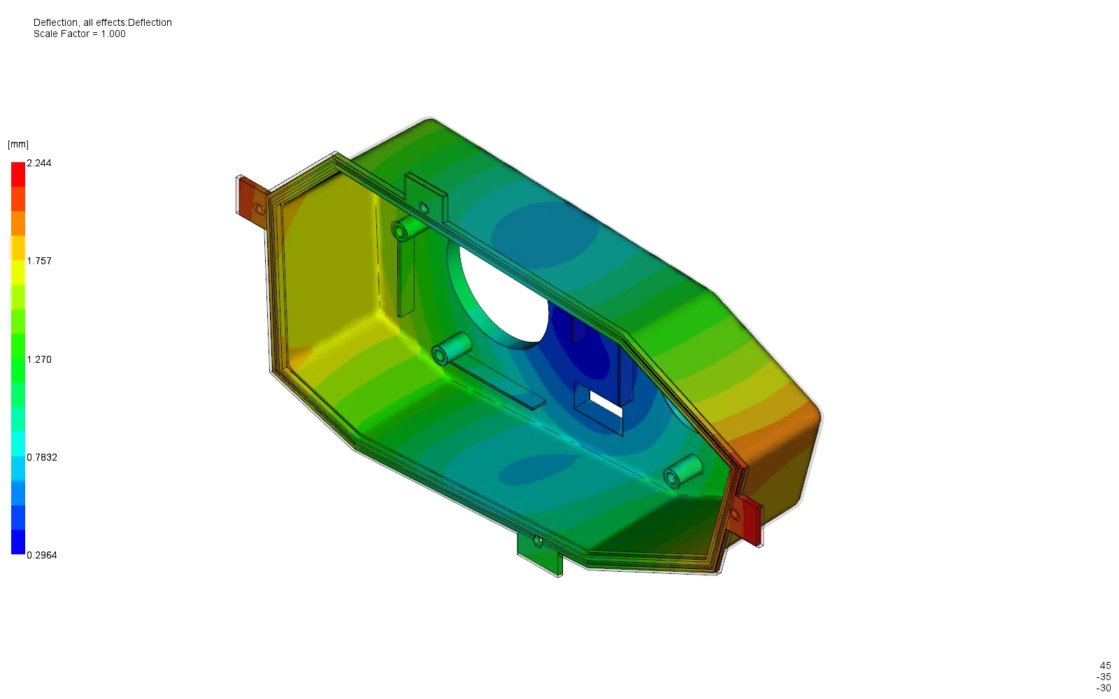
Total deflection reaches 2.244 mm at the right mounting ear. Read against a fitted plane instead, the sealing lands close to a 0.224 mm residual, which is the number a seal actually sees.
From evidence to action.
Take the mounting-tab thermal mass and the service-collar transitions as two separate design questions, and re-solve with a modelled feed system before fixing the V/P timing.
Define the sealing and mounting tolerances, then compare the revised geometry against this baseline with an explicit acceptance criterion.
Study boundaries
- Internal demonstration on an original design; no customer project or physical trial correlation is claimed.
- These are simulation outputs, not measured production performance.
- Original teaching geometry; no OEM requirement set and no supplier service qualification.
- Ideal point inlet: physical gate, runner, sprue and nozzle losses are excluded.
- Uniform mold temperature; cooling circuits and mold blocks are not modeled.
- Warp uses a two-layer aggregated mesh (solver warning 201412); mesh sensitivity at thick junctions remains open.
- No dimensional, cosmetic or sealing pass/fail claim is made without defined functional requirements.
A similar question about your part?
Send the part, the material and the question.