
Radial fan impeller
Rotational balance decided by the gate layout. A nine-blade semi-open impeller where three hot valve gates were chosen over one so that the once-per-revolution imbalance a balancing machine reads cancels by construction.
- Application
- Air moving equipment
- Material
- PA66 with 30 percent glass fiber (BASF Ultramid A3WG6)
- Method
- 3D Cool + Fill + Pack + Warp with fiber orientation
- Focus
- Rotational balance and blade-tip deflection
- Project type
- Internal demonstration
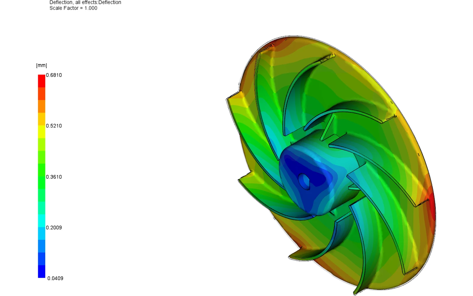
Can the gate layout remove the imbalance a balancing machine would otherwise find?
The wheel is 120 mm across with nine backward-curved blades at exactly 40 degree pitch, a 2.0 mm back plate and blades 1.5 mm at the root tapering to 1.29 mm at the tip. A perfect nine-fold geometry means any asymmetry the tool adds reads cleanly.
A single gate on the axis is impossible because the bore passes through it, so the real choice is where else to put the melt in, and how many gates to use.
A traceable engineering model.
3D Cool + Fill + Pack + Warp with fiber orientation and residual stress on an 87,848-node, 455,171-tetrahedron mesh, six elements through the 1.5 mm blade. The feed is a hot runner with three 2.0 mm valve gates at 12 mm radius, 120 degrees apart, and one cooling circuit per mold half.
Three gates on a nine-blade wheel repeat every three blades, so the fill is three-fold symmetric and its first rotational harmonic, the once-per-revolution component a balancing machine reads, cancels by construction. The alternative single gate was solved for comparison.
Read the result in context.
Three valve gates open together and the fronts merge by 25 mm radius, reaching the rim all the way round at the same instant at 0.3118 s. Against a single gate the blade-tip fill spread is 0.046 percent instead of 0.144, the fill is 25 percent faster and the peak shear is 47 percent lower.
No weld line lands on any of the nine blade roots. Rear-face hub gating fills the disc radially and the melt climbs the blades from below, so the fronts never split and rejoin at a root; the welds that do form sit at the rim and in the hub, all above 290 degC.
Total deflection is 0.681 mm, an inward radial shrink with a two-lobed axial saddle, and the blade-tip magnitude spread is 0.0791 mm. That two-fold pattern comes from the cooling, not from the gates: the modelled 30 degC water leaves the mold surface 53 K below what the grade recommends.
From evidence to action.
Keep the three-gate layout, then balance the three hot drops before cutting steel: with the feed system modelled, the blade-tip fill spread grows to 1.23 percent and one blade leads by 3.8 ms.
Run the mold at the grade's recommended 80-90 degC and re-solve, and add a core-side cooling pass under the hub; the axial tip spread and the rim saddle are two-fold patterns that come from the cooling.
Study boundaries
- Internal demonstration on an original design; no customer project or physical trial correlation is claimed.
- These are simulation outputs, not measured production performance.
- Mold modelled as a generated block only, with no plates, inserts or ejector system.
- Generic machine with no clamp limit applied and no nozzle losses.
- The three valve gates open simultaneously; no gate sequencing was simulated.
- Warpage was solved on a two-layer aggregated mesh, which suits thin walls; the 20 mm hub is not one.
- Material card as supplied, with no molding trial, no measured shrinkage and no spin or balance test.
- Every acceptance limit quoted is this study's own assumption; no drawing tolerance or balance grade was supplied.
A similar question about your part?
Send the part, the material and the question.