
Rugged handheld housing: cold runner baseline and 3D hot runner
One housing, two feed systems, one acceptance criterion. The Simmetric handheld front housing solved twice: first as the released study with sequential valve gates, modelled cooling and a sealing-rim flatness criterion, then again with the hot runner modelled as a 3D melt volume instead of beam elements.
- Application
- Rugged handheld front housing
- Material
- PC+ABS (Covestro Bayblend T85)
- Nominal wall
- 2.0 mm
- Method
- 3D Cool + Fill + Pack + Warp, solved with a beam feed and with a 3D melt volume
- Focus
- Sealing-rim flatness, then feed-system resolution
- Project type
- Internal demonstration
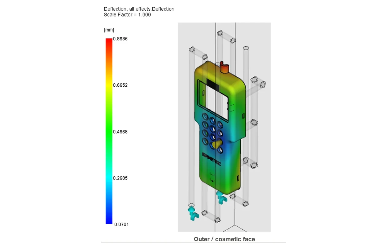
Can a complex housing hold a flat sealing rim, and does modelling the hot runner in three dimensions change that answer?
The internally developed housing brings together a display window, twelve keypad bores, a speaker grille, screw bosses and an internal rib network. Its cosmetic face must stay free of gates, and the open rim carries a stated flatness target of 0.30 mm.
That baseline study covers the whole chain: manufacturable CAD features, gate screening, a modelled hot feed system, cooling circuits and a 3D Cool + Fill + Pack + Warp run. It is the study behind the sample report offered on this site.
The second half re-solves the same housing with the runner, the drops and both gates meshed as a melt volume merged with the part, so only the feed representation changes. The nozzles were selected from the hot-runner catalogue by a selection tool rather than picked by hand.
A traceable engineering model.
Baseline: three gate configurations were screened on a consistent mesh, one centre gate, two simultaneous gates and two sequential valve gates. Sequential gating produced fewer severe welds and was selected. Two cooling circuits were modelled inside a generated mold block. The as-specified run used 25 degC coolant; a second run raised the inlet to 80 degC to find the thermal operating point.
3D feed: two-stage meshing to 203,812 nodes and 1,054,336 tetrahedra, refined to 0.4 mm on the gate land and cone, which puts about 6.5 element layers across the 2 mm gate. Mesh volume matches the CAD to 0.049 percent and every modelled region is within 0.83 percent of its CAD reference volume.
One gate is driven on time and the second on the flow front. The solver logged the second valve opening on its specified trigger node between 0.898 s, at 66.75 percent filled, and 0.920 s, which is the behaviour a beam feed cannot demonstrate.
Read the result in context.
The baseline housing fills in 1.355 s. Its maximum total deflection is 0.864 mm, but the functional sealing-rim flatness is 0.147 mm. Measuring the surface that has to seal gives a more useful answer than judging the part by the global maximum.
The modelled coolant conditions materially change the thermal state. Raising the inlet from 25 degC to 80 degC puts the mold boundary at 71.6-83.2 degC and drops the reported end-of-fill injection pressure from 56.8 to 50.5 MPa, at the cost of 30.0 s rather than 22.7 s to reach ejection temperature. Sealing-rim flatness stays inside the target at 0.165 mm.
Re-solving with a 3D melt volume barely moves the part result: total deflection 0.899 mm against 0.872 mm for the beam feed, seal-rim flatness 0.161 mm against 0.165 mm, part mass at the end of packing 50.74 g against 50.88 g, fill time 1.276 s against 1.335 s.
The feed result changes a great deal. Injection pressure at switchover drops from 63.14 to 54.42 MPa and end-of-fill pressure from 50.51 to 43.53 MPa, and only the 3D model resolves the shear field inside the feed system: 46,172 per second in the first gate region and 159,629 per second in the second, with a melt inventory of 18.245 cm3 of which 2.712 cm3 is a numerical injection pad that must be excluded from any residence figure.
The most severe cosmetic weld locations stay clustered at the speaker grille across every screened gate layout, which points the next design iteration at the grille geometry rather than at the gates.
From evidence to action.
Keep the 80 degC coolant run as the reference for process development, with the cooling time reassessed against its 30.0 s time to ejection, and keep the as-specified run as the traceable baseline. Review the speaker-grille geometry and its venting in the next iteration.
Use a resolved 3D feed when the question is about the feed system itself: gate shear, melt residence or a flow-front valve trigger. For part deflection alone the beam model gives the same answer for far less work.
Bring the mold block back before quoting any thermal or clamp number from the 3D feed run, and model the valve pin once the solver can carry it, so residence and drop shear stop being optimistic.
Study boundaries
- Internal demonstration on an original design; no customer project or physical trial correlation is claimed.
- These are simulation outputs, not measured production performance.
- The 0.30 mm sealing-rim flatness target is an assumed design requirement, not a customer drawing tolerance.
- The mold is represented by a generated steel block in the baseline; detailed plates, inserts, ejectors and venting are not modelled, and the drawn sprue routing is not a manufacturable tooling layout.
- In the 3D feed run the valve pin is not modelled: a heated region shaped as a thin annulus around the pin hangs the solver, so the melt volume is larger than the physical channel and residence and drop shear are optimistic.
- The injection pad in the 3D feed run is a numerical region, not tooling, and its volume must be excluded from any residence figure.
- The 3D feed run carries no mold block, so its internal mold temperature field is not computed; its thermal result and clamp force are not comparable with the baseline.
- Injection time is imposed rather than computed in the 3D feed run, because the automatic calculation fails with a 3D feed and a cavity injection location.
- Weld-line temperatures in the 3D feed run are reported over the whole model, including the melt channel, so they are not comparable with cavity weld temperatures.
- The available warpage outputs combine the effects; individual warpage causes are not isolated.
- No dimensional, cosmetic or sealing pass/fail claim is made without defined functional requirements.
A similar question about your part?
Send the part, the material and the question.